Electricity and magnetism
What this chapter covers
- Describe renewable and non-renewable energy sources, explain how an induced current is produced and how power stations generate electricity (6.1)
- Differentiate direct current from alternating current and use a C.R.O. to show their traces and read voltage (6.1)
- Compare step-up and step-down transformers and solve problems with Vp/Vs = Np/Ns (6.2)
- Explain the components of the transmission and distribution system, home wiring, plugs and safety components such as fuses, earth wires, MCB and ELCB (6.3)
- Define energy efficiency, calculate power, current, electrical energy and its cost in kWh, and suggest ways to save electricity (6.4)
6.1Generation of electricity
Energy sources
Can be replaced continually and will never deplete.
Hydro, wave, solar, tidal, wind, biomass and geothermal energy.
Cannot be replaced and will deplete.
Nuclear energy, coal, natural gas and petroleum (diesel).
Malaysia uses both groups. Examples from the textbook: Bakun (hydro, Sarawak), Sultan Azlan Shah, Manjung, Perak (coal), Tuanku Jaafar, Negeri Sembilan (natural gas), Gelugor, Pulau Pinang (diesel) and a biomass station in Sabah.
How a generator makes current
The magnetic field lines can be cut in two ways, and both give a deflection on the galvanometer:
- The wire or coil moves through the space between the magnetic poles.
- The magnet moves past a stationary wire or coil.
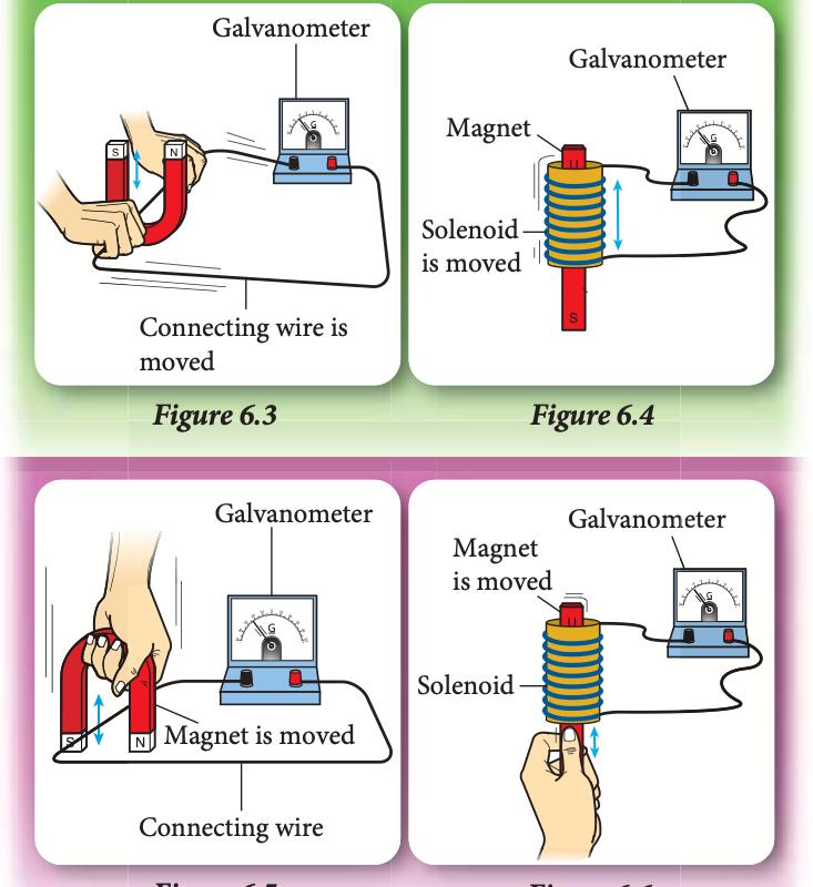
Textbook Figures 6.3–6.6, p. 164.
Show answerHide answer
Power stations
Most power stations drive a turbine that turns a generator. What differs is how the turbine is turned.
| Power station | What turns the turbine | Energy changes |
|---|---|---|
| Thermal (diesel, natural gas, coal) | Steam from boiling water | Chemical → heat → kinetic → electrical |
| Nuclear | Steam from a nuclear reaction | Nuclear → heat → kinetic → electrical |
| Biomass | Steam from burning methane produced by biomass | Chemical → heat → kinetic → electrical |
| Hydroelectric | Water flowing from a high dam to a lower level | Gravitational potential → kinetic → electrical |
| Wind | Moving air turns the blades | Kinetic → electrical |
| Solar | No turbine: solar panels change light directly to electricity | Solar (light) → electrical |
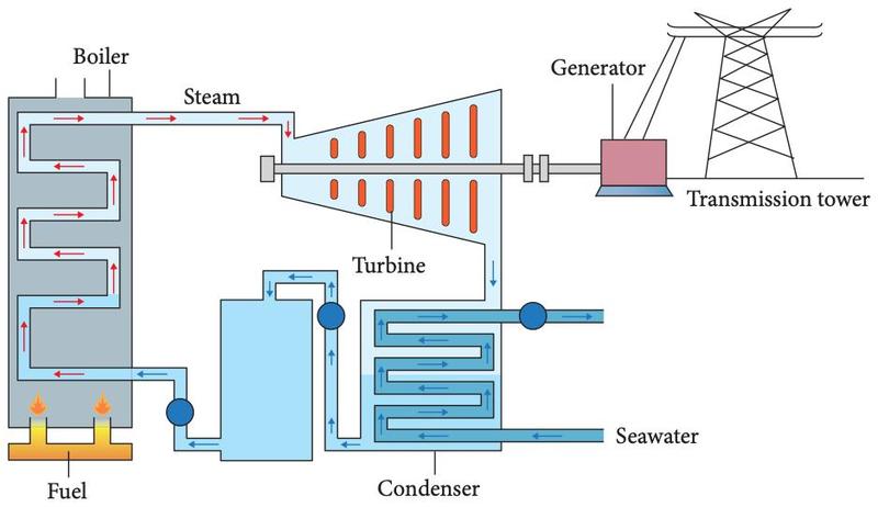
Textbook Figure 6.8, p. 167.
Direct current and alternating current
| Direct current (d.c.) | Alternating current (a.c.) | |
|---|---|---|
| Direction | Flows in one direction only | Constantly reverses direction |
| Sources | Solar cells, accumulators, batteries (dry cells) | Generators in power stations, the 240 V mains |
| Devices | Torchlight, calculator, toy car | Bread toaster, hair dryer, air conditioner |
| Trace on a C.R.O. | A straight horizontal line (fixed voltage) | A wave that rises and falls above and below zero |
Cathode ray oscilloscope (C.R.O.)
A C.R.O. is an electronic device that shows the shape of the graph, the direction of the current and the change in voltage for d.c. and a.c. The voltage is the displacement of the trace multiplied by the Y-gain setting.
- Y-gain changes the height of the light spot; Y-shift and X-shift move the spot vertically and horizontally.
- Time-base makes the light spot sweep across the screen horizontally.
- Intensity controls brightness; focus controls sharpness.
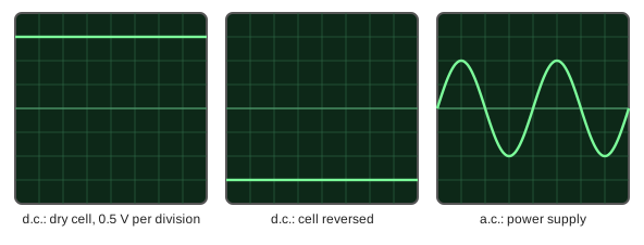
Voltage = displacement × Y-gain = 3 × 0.5 = 1.5 V.
Show answerHide answer
6.2Transformer
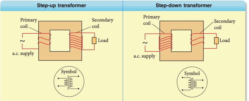
Textbook Table 6.1, p. 178.
| Step-up transformer | Step-down transformer | |
|---|---|---|
| Voltage | Vs is higher than Vp | Vs is lower than Vp |
| Turns | Np is less than Ns | Np is more than Ns |
| Example | Before transmission at the power station | Mobile phone charger, ceiling fan regulator |
A transformer only works with alternating current. A laminated core (layers of soft iron separated by insulators) reduces the eddy current and makes the transformer more efficient.
The transformer equation
Vp = primary (input) voltage, Vs = secondary (output) voltage, Np and Ns = number of turns of the primary and secondary coils.
240 / 40 = 120 / Ns → Ns = 120 × 40 / 240 = 20 turns. Since Vs is less than Vp this is a step-down transformer.
Vs = Vp × Ns / Np = 12 × 2 000 / 500 = 48 V (step-up).
Show answerHide answer
6.3Transmission and distribution of electricity
From the power station to your home
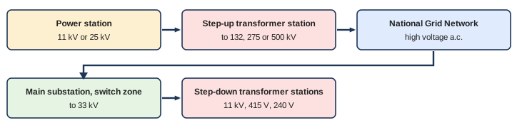
Based on textbook Figure 6.28, p. 184.
| Component | Function |
|---|---|
| Power station | Generators produce a.c. at 11 kV or 25 kV |
| Step-up transformer station | Increases the voltage to 132 kV, 275 kV or 500 kV |
| National Grid Network | Network of transmission cables carrying high voltage a.c. over long distances |
| Switch zone (at the main substation) | Sends electricity to the branch substation when needed; lets power stations and grids be closed for maintenance without cutting the supply |
| Step-down transformer station (main and branch substations) | Reduces the voltage in stages for the consumer: 33 kV for heavy industry, 11 kV for light industry, 415 V for offices and 240 V for homes |
Strong electromagnetic fields are produced around high voltage cables on the National Grid pylons. A compass needle near the pylons is affected, and residents have raised health concerns.
Wiring in Malaysia
- Single-phase wiring: suitable for use up to 10 kW or 50 A, such as rural homes.
- Three-phase wiring: more stable and reliable; used in commercial and industrial areas above 10 kW or 50 A.
In a home, the live wire (240 V) and neutral wire (0 V) come from the main cable, through the electric meter (measures the units used) and the consumer unit with the main switch, the ELCB (cuts the circuit when too much current flows through it) and MCBs (separate the final circuits for the lighting, power, heating and air-conditioning).
Plugs and wire colours
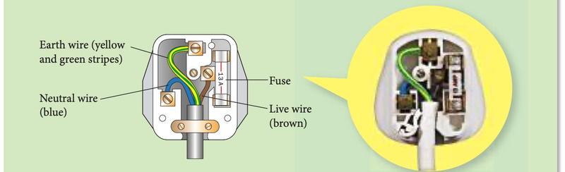
Textbook Figure 6.32, p. 190.
| Wire | Colour |
|---|---|
| Live | Brown |
| Neutral | Blue |
| Earth | Green and yellow stripes |
A 3-pin plug (kettle, iron) has an earth pin. A 2-pin plug (hair dryer, electric toothbrush) has no earth wire.
Safety components
| Component | What it does |
|---|---|
| Fuse | A short, fine wire that heats up and melts when the current is more than its value, cutting off the supply |
| Earth wire | Connects the metal casing to Earth; if the casing becomes live, a large current flows to Earth and melts the fuse |
| MCB (miniature circuit breaker) | Cuts off the circuit when the current is too large; can be reset |
| ELCB (earth leakage circuit breaker) | Breaks the circuit when too much current flows through it, such as a leakage of current to Earth |
| Lightning conductor | Carries lightning safely to Earth from a building |
| Switch | Opens and closes the circuit; fitted in the live wire |
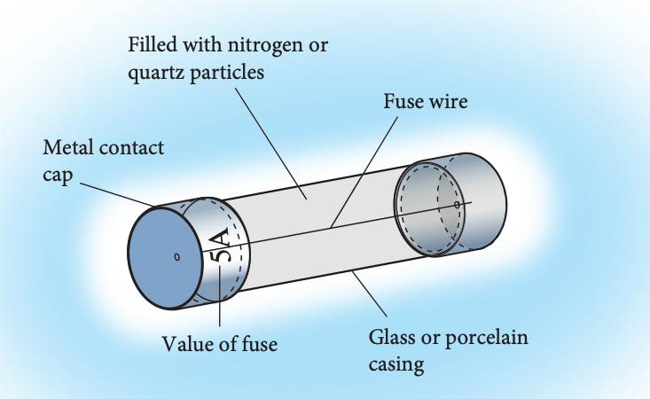
Textbook Figure 6.33, p. 191.
A 10 A fuse is too low (it would melt every time). A 13 A fuse is slightly higher, so it is the 13 A fuse.
Show answerHide answer
6.4Calculating the cost of electricity consumption
Energy efficiency
Energy efficiency = (useful energy output ÷ energy input) × 100%
Efficiency = 8 / 100 × 100% = 8%.
| Lighting device | Maximum energy changed to light | Lasts about |
|---|---|---|
| Filament lamp | about 10% | 1 000 hours |
| Energy saving lamp (CFL) | about 50% | 8 000 hours |
| LED lamp | about 90% | 20 000 to 50 000 hours |
The Energy Commission (EC) puts an energy efficiency label with 1 to 5 stars on appliances. More stars means more energy saving; choose appliances with more stars.
Power, current, voltage and energy
| Quantity | Equation | S.I. unit |
|---|---|---|
| Electric power, P | P = E ÷ t (energy ÷ time) | watt, W (1 W = 1 J s−1) |
| Electric current, I | I = Q ÷ t (charge ÷ time) | ampere, A (charge in coulomb, C) |
| Voltage, V | V = E ÷ Q (energy ÷ charge) | volt, V |
| Power, voltage and current | P = V × I | W = V × A |
I = P ÷ V = 2 200 ÷ 240 = 9.17 A.
Cost of electrical energy
Electrical energy (kWh) = power (kW) × time (h)
Cost = number of units × rate per unit
Energy = 2 × (10 ÷ 60) = 1/3 kWh. Cost = 1/3 × 21 = 7 sen.
Ways to save electrical energy
- Use appliances with more stars on the energy efficiency label, and LED or CFL lamps instead of filament lamps.
- Switch off lights and appliances that are not in use.
- Use natural lighting and good ventilation. A green building uses efficient ventilation, natural lighting and solar panels to cut its energy cost.
Show answerHide answer
Summary
| Remember | Key fact |
|---|---|
| Induced current | Produced when magnetic field lines are cut by a wire or coil, by moving the wire or the magnet |
| d.c. and a.c. | d.c. flows one way (cells, batteries); a.c. keeps reversing (power station generators) |
| C.R.O. | Shows the shape, direction and voltage change; voltage = displacement × Y-gain |
| Transformer | Works with a.c. only; Vp/Vs = Np/Ns; step-up has Ns more than Np |
| Transmission | Power station → step-up station → National Grid → switch zone → step-down stations → consumers |
| Wires | Live brown, neutral blue, earth green and yellow |
| Fuse | Value slightly higher than the normal current; melts when current is too large |
| Power and energy | P = VI; energy (kWh) = power (kW) × time (h); cost = units × rate |
| Efficiency | Useful output ÷ input × 100% |