myUASARevision for UASA
Mathematics notes, chapter 7

Plans and Elevations

Textbook Mathematics Form 3 (DLP), pages 168–197

What this chapter covers

  • Identify horizontal, vertical and inclined planes, and name a normal to a plane (7.1)
  • Draw the orthogonal projection of a line, a plane shape and a solid on a horizontal or a vertical plane (7.1)
  • Compare an object with its orthogonal projections in terms of the length of sides and the size of angles (7.1)
  • Draw the plan and the front and side elevations of an object to scale, using solid, dashed and construction lines, in the four-quadrant layout (7.2)
  • Synthesise a plan and elevations to sketch the three-dimensional object (7.2)
  • Solve problems involving plans, elevations, lengths, volumes and ratios (7.2)

An architect cannot show a whole building in one flat picture, so the building is drawn from the top and from the sides. The Diamond Building (the Energy Commission headquarters) in Putrajaya looks different when it is viewed from different directions, so its design is described with flat drawings made from the top and from the sides. In this chapter you will learn how a three-dimensional object is projected onto a flat plane, how to draw its plan and elevations to scale, and how to build the object again in your mind from those drawings.

EnglishBahasa Melayu
orthogonal projectionunjuran ortogon
planpelan
elevationdongakan
normal to a planenormal kepada satah
horizontal plane, vertical plane, inclined planesatah mengufuk, satah mencancang, satah condong
solid line, dashed linegaris padu, garis sempang
quadrantsukuan
scaleskala
full scaleskala penuh

7.1Orthogonal projections

Planes and normals
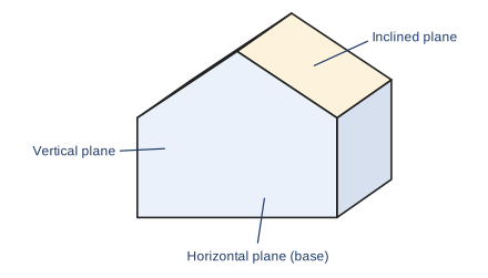
A plane is a flat surface of an object. A plane can be horizontal (level, like a floor), vertical (upright, like a wall) or inclined (slanted, like a roof).
A house-shaped prism with its base labelled horizontal plane, its end wall labelled vertical plane and its roof labelled inclined plane
A prism has all three kinds of plane.
A normal to a plane is a straight line that is perpendicular to the plane. It makes a right angle with every line that lies on the plane.
Example (textbook Example 1, p. 170): naming normals
In a cuboid PQRSTUVW with base PQRS, the line TS rises from S and is perpendicular to the base. So TS is a normal to the plane PQRS at point S. The same line is also a normal to the plane TUVW, but there its foot is T, so it is named ST.
The order of the letters matters: the foot of the normal is written last, as in TS, because it meets the plane PQRS at S.
To find a normal to a plane, look for an edge of the solid that meets the plane at a right angle. In a cuboid, the four upright edges are normals to the top and bottom faces.

What an orthogonal projection is

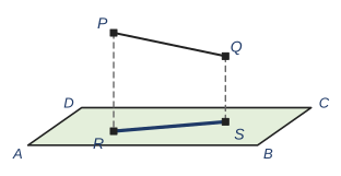
Orthogonal projections are the images formed on a plane when the projecting lines from the object are perpendicular (normals) to the plane.
A line PQ above the horizontal plane ABCD with dashed normals PR and QS and the projection RS drawn thick on the plane
PR and QS are normals to the plane ABCD. RS is the orthogonal projection of the line PQ on the plane.

For a line, drop a normal from each end to the plane and join the two feet. For a solid, do this for every vertex, then join the feet in the same order.
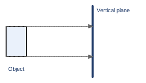
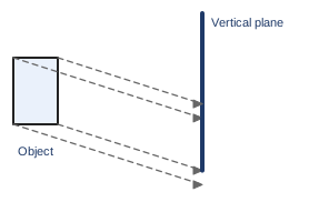
A rectangle with two horizontal dashed lines going to a vertical plane at right angles
Projecting lines are normals: an orthogonal projection.
A rectangle with two slanted dashed lines going to a vertical plane
Projecting lines are slanted: not an orthogonal projection.
A projection is orthogonal only when the projecting lines are normal to the plane. Slanted lines still make a shadow, but it is not an orthogonal projection (textbook Example 3, p. 172).

Drawing an orthogonal projection

  1. Decide the type of plane (horizontal or vertical) and the viewing direction.
  2. Draw normal lines from every vertex to the plane.
  3. Join the points where the normals meet the plane, in order.
  4. Redraw the shape with the actual measurements and label the vertices (a vertex hidden behind another is written after a slash, such as E/D).
Example (based on textbook Example 5, p. 176): a cylinder
A cylinder of diameter 4 cm and height 3 cm stands on a horizontal plane.
(a) Viewed from above (on the horizontal plane): a circle of diameter 4 cm.
(b) Viewed from the side (on a vertical plane): a rectangle 4 cm wide and 3 cm high.
A cone of base diameter 6 cm and height 4 cm stands on its base on a horizontal plane. What are its orthogonal projections on (a) the horizontal plane viewed from above and (b) a vertical plane viewed from the side?
Show answerHide answer
(a) A circle of diameter 6 cm, with a dot at its centre (the apex is directly above the centre).
(b) An isosceles triangle with base 6 cm and height 4 cm.

Comparing an object with its projection

The length of a side and the size of an angle in the projection may stay the same or may change, depending on the viewing direction.

  • A side that is parallel to the projection plane keeps its actual length.
  • A side that is inclined to the plane becomes shorter.
  • A side that is perpendicular to the plane becomes a point.
  • An angle on a face that is parallel to the plane keeps its size. An angle on an inclined face may become larger or smaller.
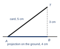
A card of length 5 cm leaning so that one end is 3 cm above the ground; its projection on the ground is 4 cm
An inclined 5 cm card has a projection of only 4 cm (3-4-5 triangle).
Example (based on textbook Example 6, p. 181): a ramp
A right prism has a rectangular base PQRS lying on a horizontal plane, 8 cm long and 2 cm wide, and a vertical rectangular end PSUT 8 cm long and 3 cm high. The sloping face is TUQR.
Viewed from above, the plan is a rectangle 8 cm by 2 cm. The lengths PQ and QR are the actual lengths and the right angles stay right angles. The sloping edge TQ is inclined, so its projection (PQ = 2 cm) is shorter than TQ itself, which is √(2² + 3²) = √13 ≈ 3.6 cm.
Do not assume that every length in a projection is the actual length. Only sides parallel to the plane are drawn at their true size.
A 10 cm rod leans so that its top is 8 cm above the ground and its lower end touches the ground. How long is its orthogonal projection on the ground?
Show answerHide answer
√(10² − 8²) = √36 = 6 cm. The projection is shorter than the rod because the rod is inclined.

7.2Plans and elevations

The orthogonal projection on a horizontal plane, seen from the top, is called a plan. The orthogonal projections on vertical planes, seen from the front or the side, are called elevations (front elevation and side elevation).

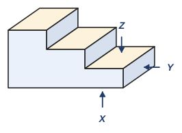
Plans and elevations are drawn to full scale (actual size) or to a scale given in the question. In the textbook, the object stands on a horizontal plane, the plan is seen from Z (above), the front elevation from X (in front) and the side elevation from Y (from the right-hand side in method 1, from the left-hand side in method 2).

Line types
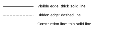
Three line samples: a thick solid line for visible edges, a dashed line for hidden edges, a thin line for construction
If you could see an edge from the viewing direction, draw it solid. If it is hidden behind the object, draw it dashed. Use thin lines only as guides.

Worked example: a house-shaped prism

The prism below has a rectangular base 6 cm by 4 cm, upright walls 3 cm high and a ridge 5 cm above the floor in the middle.
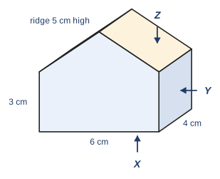
House-shaped prism, 6 cm wide, 4 cm deep, walls 3 cm high, ridge 5 cm high, with viewing directions X, Y and Z
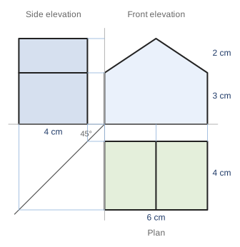
Plan: rectangle 6 by 4 with a line down the middle; front elevation: a pentagon; side elevation: a rectangle 4 by 5 with a line at 3 cm
Plan (below), front elevation (right) and side elevation (left), drawn in the four-quadrant layout.
  • Plan from Z: a rectangle 6 cm by 4 cm. The ridge is a solid line down the middle, at 3 cm from each side.
  • Front elevation from X: a pentagon (a 6 cm by 3 cm rectangle with a triangle of height 2 cm on top).
  • Side elevation from Y: a rectangle 4 cm by 5 cm. The line at 3 cm is where the wall meets the roof; it is visible, so it is solid.

The four-quadrant layout
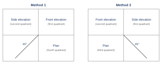
Two diagrams of four quadrants. Method 1 has the side elevation top left, front elevation top right and plan bottom right. Method 2 has the front elevation top left, side elevation top right and plan bottom left, with the 45 degree line bottom right in the fourth quadrant. In method 1 the 45 degree line is in the third quadrant.
  1. (Method 1) Draw the plan in the fourth quadrant (bottom right).
  2. Draw the front elevation directly above the plan (first quadrant), using thin vertical lines from the plan so the widths match.
  3. Draw a 45° line from the centre point into the third quadrant. Project the plan across to the 45° line, then straight up, and use thin lines from the front elevation across for the heights. This gives the side elevation in the second quadrant (method 1, viewed from the right).
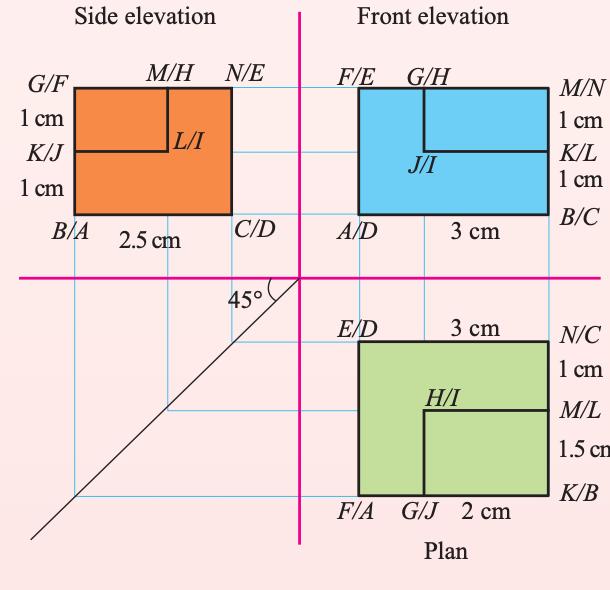
In method 1 the side elevation is seen from the right and sits to the left of the front elevation. In method 2 it is seen from the left and sits to the right; the plan is then drawn in the third quadrant, under the front elevation, and the 45° line is in the fourth quadrant.
Textbook diagram of a front elevation, side elevation and plan in four quadrants joined by thin projection lines and a 45 degree line

Textbook figure: Mathematics Form 3 (DLP) textbook, p. 187 (Example 9).

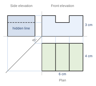
Hidden edges: a block with a channel
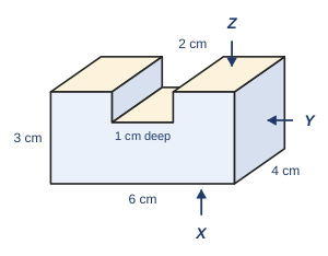
A block 6 cm by 4 cm by 3 cm with a channel 2 cm wide and 1 cm deep cut along its whole depth in the top
Plan: rectangle with two vertical lines; front elevation: rectangle with a notch in the top middle; side elevation: rectangle 4 by 3 with a dashed line at 2 cm
  • Plan: both edges of the channel are visible from above, so two solid lines.
  • Front elevation: the channel shows as a notch, 2 cm wide and 1 cm deep.
  • Side elevation: the channel's floor is hidden inside the block, so it is drawn as a dashed line at 2 cm from the bottom.
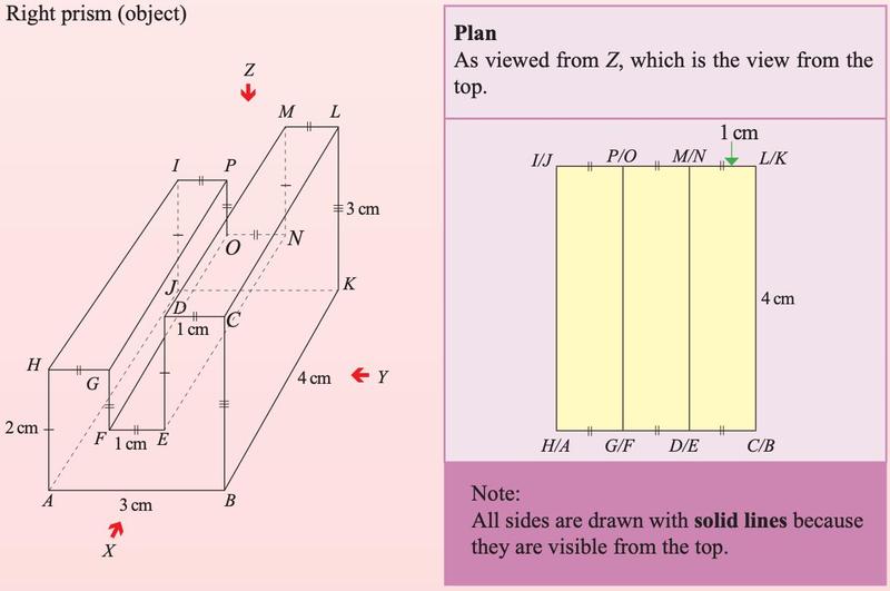
Textbook drawing of a right prism with a channel and its plan, which has solid lines for every visible side

Textbook figure: Mathematics Form 3 (DLP) textbook, p. 182.

The block above is viewed from the left (the opposite side to Y). Is the line at 2 cm solid or dashed? What is the volume of the block?
Show answerHide answer
Still dashed: the channel runs the whole depth of the block and is hidden from either side.
Volume = 6 × 4 × 3 − 2 × 4 × 1 = 72 − 8 = 64 cm³.
Forgetting a hidden edge, or drawing it solid. A line that cannot be seen from the viewing direction must be dashed.

Sketching the object from its plan and elevations

Plan and elevations share measurements, so together they fix the shape. To rebuild the object:

  1. Sketch the three views on their planes using the given measurements.
  2. Project each surface out from its view so that the matching surfaces meet.
  3. Join the vertices and label them with the letters of the views.
  4. Write the lengths on the sketch.
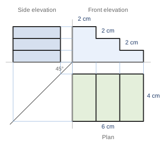
Example (based on textbook Example 9, p. 187): a three-step block
Plan: rectangle 6 by 4 with two vertical lines; front elevation: staircase falling to the right with steps of height 3, 2 and 1; side elevation: rectangle 4 by 3 with lines at 1 and 2
The plan is a rectangle with two lines, so the top has three flat parts, each 2 cm wide. The front elevation shows their heights (3, 2 and 1 cm). The side elevation has lines at 1 cm and 2 cm, which are the risers of the steps. So the object is a block with three steps, each 2 cm wide and 4 cm deep.
Oblique sketch of the three-step block
Use the front elevation of the block above to calculate its volume.
Show answerHide answer
Area of the front elevation = 2 × 3 + 2 × 2 + 2 × 1 = 12 cm². Volume = 12 × 4 = 48 cm³.

Solving problems

Combine the measurements from the views with area and volume formulae. Volume of a prism = area of uniform cross section × length. A triangular piece removed from a block has volume ½ × base × height × length.

Example (based on textbook Example 11, p. 190)
A block was a cuboid 9 cm long, 4 cm wide and 6 cm high. A right prism with a triangular cross section (base 4 cm, height 3 cm) and length 4 cm was cut off one top edge. Find (a) the volume removed, (b) the ratio of the volume removed to the volume left.
(a) ½ × 4 × 3 × 4 = 24 cm³
(b) Cuboid = 9 × 4 × 6 = 216 cm³. Left = 216 − 24 = 192 cm³.
Ratio = 24 : 192 = 1 : 8
Check the slanting edge in the front elevation with Pythagoras: 4² + 3² = 5², so the slope is 5 cm. The slope appears with its actual length only in the view where it is parallel to the plane.
The plan of a solid is a circle of diameter 6 cm with a dot in its centre. The front elevation is a rectangle 6 cm wide and 5 cm high with an isosceles triangle of height 4 cm on top. (a) Describe the solid. (b) How long is each slanting side of the triangle?
Show answerHide answer
(a) A cone of height 4 cm standing on a cylinder of height 5 cm; both have diameter 6 cm.
(b) √(3² + 4²) = 5 cm.