Electromagnetism
What this chapter covers
- Explain the force on a current-carrying conductor in a magnetic field, the catapult field and Fleming's left-hand rule (4.1.1, 4.1.2)
- Describe the factors that affect the magnitude of the force and the turning effect of a current-carrying coil (4.1.3, 4.1.4)
- Explain how a direct current motor works and what affects its speed; compare brushed and brushless motors (4.1.5, 4.1.6)
- Explain electromagnetic induction and the factors affecting the induced e.m.f.; state Faraday's law (4.2.1, 4.2.2)
- Use Fleming's right-hand rule and Lenz's law to find the direction of induced current (4.2.3)
- Compare direct current and alternating current generators (4.2.4)
- Explain how a transformer works and solve problems on ideal transformers and efficiency (4.3.1, 4.3.2)
- Explain energy loss in transformers, and the role of transformers in transmission and distribution of electricity (4.3.3, 4.3.4)
4.1Force on a current-carrying conductor in a magnetic field
When a current-carrying conductor is placed in a magnetic field it experiences a force. The direction of the force depends on the direction of the current and the direction of the magnetic field.
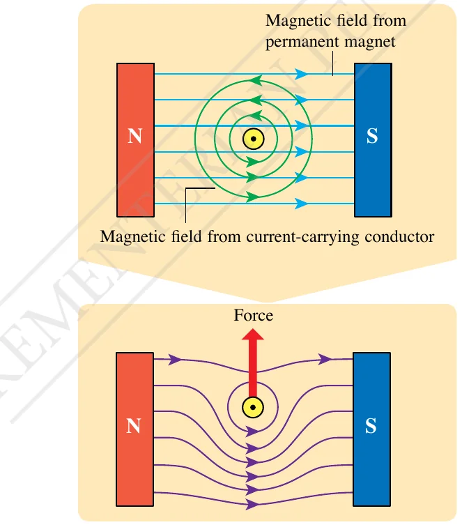
Figure: Physics Form 5 (DLP) textbook, Figure 4.3, p. 138.
Fleming's left-hand rule
| Finger | Shows |
|---|---|
| First (index) finger | Direction of the magnetic field, from north to south |
| Second (middle) finger | Direction of the electric current |
| Thumb | Direction of the force, and so the motion of the conductor |
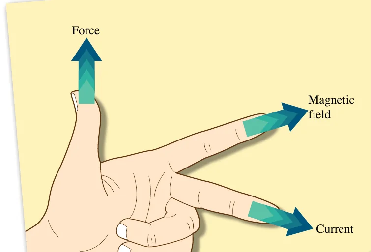
Figure: Physics Form 5 (DLP) textbook, Figure 4.4, p. 139.
Magnitude of the force
The force increases when the current increases and when the strength of the magnetic field increases (for example by using stronger magnets or bringing the poles closer). In the textbook experiment the force shows up as a larger reading on an electronic balance.
Index finger to the right (N to S), middle finger into the page. The thumb points downwards. If the current is reversed (out of the page) the force is upwards.
Current-carrying coil and the d.c. motor
A coil in a magnetic field has forces of equal size but opposite direction on its two opposite sides. This pair of forces gives a turning effect and the coil rotates about its axis. This is the working principle of the direct current (d.c.) motor, which changes electrical energy to kinetic energy.
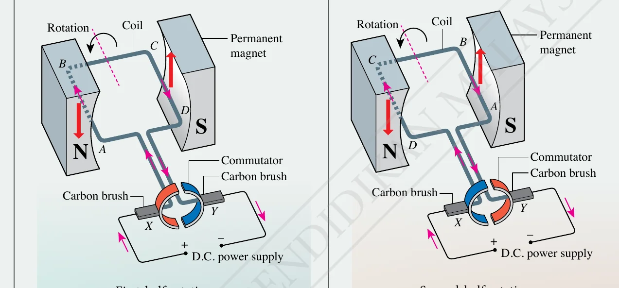
Figure: Physics Form 5 (DLP) textbook, Figure 4.13, p. 144.
The speed of rotation of a motor increases when the current in the coil increases, the magnetic field is stronger, or the coil has more turns.
Brushed and brushless motors
| Brushed motor | Brushless motor | |
|---|---|---|
| Rotating part | Coil rotates, magnet stationary | Magnet rotates, coil stationary |
| Brushes and commutator | Carbon brushes wear out through friction | None, so no friction |
| Sparking | Sparks at commutator | No sparking |
| Noise | Louder | Quieter |
Show answerHide answer
4.2Electromagnetic induction
The conductor must cut magnetic field lines (magnetic flux). A galvanometer deflects only while there is relative motion. If the magnet and the conductor are stationary, or move together with the same velocity, there is no induction.
Factors affecting the induced e.m.f.
- The speed of relative motion between magnet and conductor.
- The strength of the magnetic field.
- The number of turns of the solenoid.
Faraday's law: the magnitude of the induced e.m.f. is directly proportional to the rate of cutting of magnetic flux.
Direction of the induced current
Straight wire: Fleming's right-hand rule. Thumb for the motion of the wire, first finger for the magnetic field, second finger for the induced current. Use the right hand for a generator.
Solenoid: Lenz's law. The induced current flows in a direction that opposes the change of magnetic flux that causes it.
| Magnet movement | Pole induced at the nearer end of the solenoid | Effect |
|---|---|---|
| N pole pushed in | North | Repels the magnet |
| N pole pulled out | South | Attracts the magnet |
| S pole pushed in | South | Repels the magnet |
| S pole pulled out | North | Attracts the magnet |
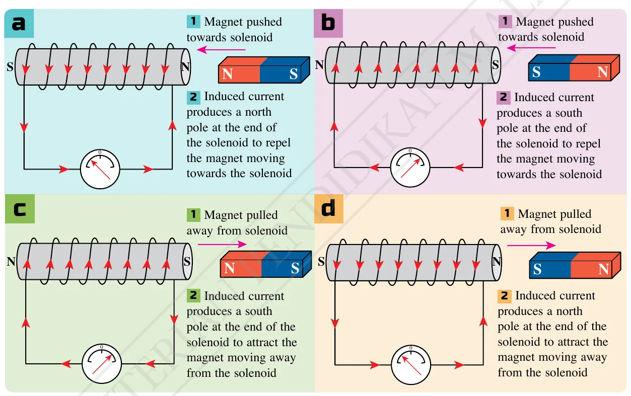
Figure: Physics Form 5 (DLP) textbook, Figure 4.28, p. 159.
Generators
| d.c. generator | a.c. generator | |
|---|---|---|
| Coil ends connected to | Split-ring commutator | Two slip rings |
| Output | Direct current | Alternating current |
| Both | Coil is turned by an external force, cuts magnetic flux, e.m.f. is induced | |
A faster rotation cuts flux at a greater rate, so the induced e.m.f. is larger (Faraday's law).
Show answerHide answer
4.3Transformers
A transformer changes the value of an alternating voltage. It works only with a.c. because only a changing current makes a changing magnetic field in the core.
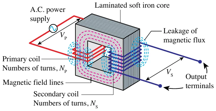
Figure: Physics Form 5 (DLP) textbook, Figure 4.32, p. 163.
Working principle. The a.c. in the primary coil produces a magnetic field that changes in size and direction. The soft iron core links this flux to the secondary coil. The changing flux induces an alternating voltage across the secondary coil.
Step-up: NS > NP, so VS > VP. Step-down: NS < NP, so VS < VP.
Ideal transformer and efficiency
Efficiency = (output power / input power) × 100% = (VSIS / VPIP) × 100%. An ideal transformer has 100% efficiency, so VPIP = VSIS.
NP = 240 / 18 × 60 = 800 turns. IS = 27 / 18 = 1.5 A. IP = 27 / 240 = 0.1125 A.
Energy loss and how to reduce it
| Cause of loss | Way to reduce it |
|---|---|
| Resistance of the coils (heating) | Use thicker copper wire |
| Eddy currents in the core | Use a laminated core of thin insulated sheets |
| Hysteresis (repeated magnetising) | Use soft iron for the core |
| Leakage of magnetic flux | Wind the secondary coil on top of the primary coil |
Eddy currents are useful in an induction cooker: a high-frequency changing field induces eddy currents in the base of the pan, which heats it.
Transmission of electricity
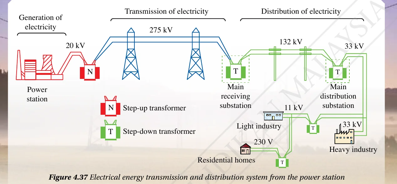
Figure: Physics Form 5 (DLP) textbook, Figure 4.37, p. 167.
High voltage means small current for the same power, so less energy is lost as heat in the cables (P = I2R).