Electronics
What this chapter covers
- Explain thermionic emission and the production and properties of cathode rays (5.1.1, 5.1.2)
- Calculate the maximum velocity of an electron accelerated across a potential difference using eV = ½mv² (5.1.3)
- Explain the function of a semiconductor diode and forward and reverse bias (5.2.1)
- Explain half-wave and full-wave rectification and how a capacitor smooths the output (5.2.2)
- Describe the terminals and circuits of npn and pnp transistors (5.3.1)
- Explain how a transistor acts as a current amplifier and calculate the amplification factor (5.3.1)
- Explain how a transistor with a potential divider works as a light-controlled and a heat-controlled automatic switch (5.3.2)
5.1Electron
A metal such as a tungsten filament has many free electrons. When the filament is heated by a 6 V supply, the electrons gain enough kinetic energy to leave the metal surface. An extra high tension (E.H.T.) supply then makes the anode positive, so the emitted electrons are pulled across to it as a fast beam, which completes the circuit and gives a reading on the milliammeter.
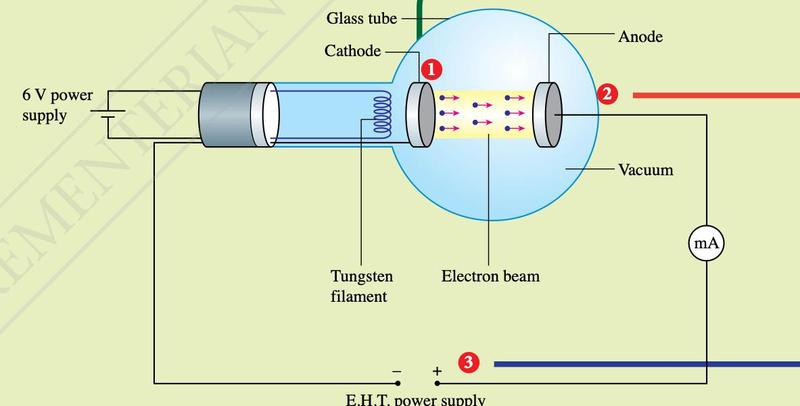
Figure: Physics Form 5 (DLP) textbook, Figure 5.1, p. 174.
- The tube is a vacuum so that the electrons are not stopped by air molecules; they reach the anode with no energy loss and at maximum speed.
- If the E.H.T. connection is reversed, the milliammeter shows no reading: the anode no longer attracts the electrons.
Properties of cathode rays
| Apparatus | Observation | Conclusion |
|---|---|---|
| Maltese cross tube | A sharp shadow of the cross on the fluorescent screen | Cathode rays travel in straight lines |
| Maltese cross tube | The screen glows where the rays strike it | Cathode rays cause fluorescence and carry energy |
| Deflection tube | The beam bends towards the positive plate in a curved (parabolic) path | Cathode rays are negatively charged |
| Maltese cross tube with a magnet | The shadow moves; the direction follows Fleming's left-hand rule | Cathode rays are deflected by a magnetic field |
Velocity of an electron
The electrical potential energy gained by an electron crossing a potential difference V is eV. In a vacuum all of it becomes kinetic energy:
e = 1.6 × 10⁻¹⁹ C, m = 9.11 × 10⁻³¹ kg
Kinetic energy = eV = 1.6 × 10−19 × 550 = 8.8 × 10⁻¹⁷ J.
vmax = √(2 × 8.8 × 10−17 / 9.11 × 10⁻³¹) = 1.39 × 10⁷ m s−1.
Show answerHide answer
5.2Semiconductor diode
In p-type material the majority charge carriers are holes (positive); in n-type they are electrons. Foreign atoms are added to pure semiconductor by doping.
| Forward biased | Reverse biased | |
|---|---|---|
| Connection | Positive terminal to anode (p), negative to cathode (n) | Positive terminal to cathode, negative to anode |
| Depletion layer | Becomes thinner | Becomes thicker |
| Resistance of diode | Very small | Very high |
| Current and bulb | Current flows; bulb lights | No current; bulb does not light |
Rectification
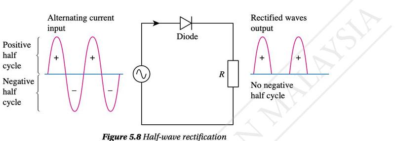
Figure: Physics Form 5 (DLP) textbook, Figure 5.8, p. 184.
Full-wave rectification uses four diodes in a bridge rectifier. Both half cycles are made to flow the same way through the load.
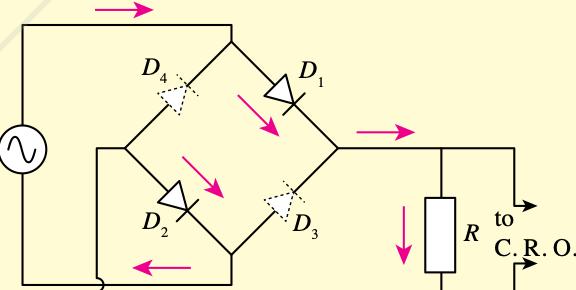
Figure: Physics Form 5 (DLP) textbook, Figure 5.9, p. 184.
Smoothing with a capacitor
The rectified output is d.c. but it rises and falls. A capacitor connected in parallel with the load R smooths it: it charges and stores energy while the potential difference rises, and discharges through R while the potential difference falls, so the output does not drop to zero.
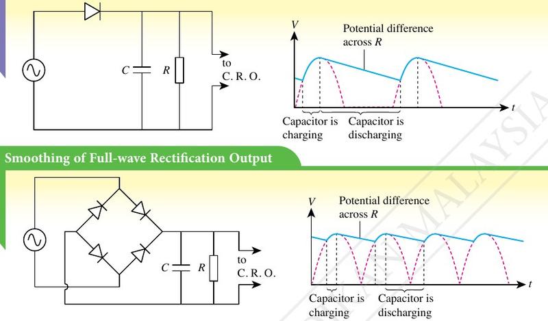
Figure: Physics Form 5 (DLP) textbook, Figure 5.12, p. 186.
Show answerHide answer
5.3Transistor
There are two types, npn and pnp. In the symbol the arrow is on the emitter: it points out (B to E) for npn and in (E to B) for pnp. In a pnp circuit the battery polarity of both the base and collector circuits is reversed, so all the currents reverse too.
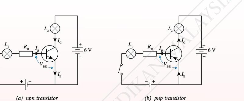
Figure: Physics Form 5 (DLP) textbook, Figure 5.13, p. 188.
- With no base current (IB = 0) there is no collector current, so the lamp in the collector circuit stays off.
- The base resistor RB is large to limit IB and stop the transistor overheating.
- A minimum base-emitter voltage VBE is needed: 0.7 V for silicon and 0.3 V for germanium.
Transistor as a current amplifier
A small change in IB gives a large change in IC. The graph of IC against IB is a straight line through the origin; its gradient is the amplification factor:
In the textbook graph the gradient is 78.0 mA / 0.5 mA = 156, so a 1 mA change in the base current causes a 156 mA change in the collector current.
Transistor as an automatic switch
No current flows in the collector circuit unless a base current flows, so the transistor can switch a lamp, LED or bell on and off. A potential divider supplies the base voltage:
| Switch | Sensor | When it switches on |
|---|---|---|
| Light-controlled (street light) | Light-dependent resistor (LDR): resistance high in the dark, low in bright light | In the dark RLDR is large, so VLDR rises above VBE; IB flows and the lamp lights |
| Heat-controlled (alarm) | Thermistor: resistance falls as temperature rises | When hot, the thermistor voltage falls, so the voltage across the fixed resistor R rises above VBE; IB flows and the bell rings |
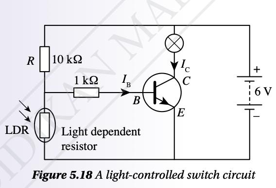
Figure: Physics Form 5 (DLP) textbook, Figure 5.18, p. 191.
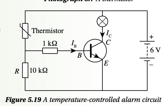
Figure: Physics Form 5 (DLP) textbook, Figure 5.19, p. 191.
VLDR = 100 / (10 + 100) × 6 = 5.45 V, well above 0.7 V, so the transistor turns on.